


Introduction
A Control Plan (CP) is a crucial document used in the production process to ensure product compliance with requirements. It is an integral part of the APQP (Advanced Product Quality Planning) process and is used in the automotive industry (IATF 16949), aerospace (AS 9100), and other sectors that incorporate APQP methodologies.
The control plan outlines specific actions that shall be taken by operators, quality control personnel, or anyone involved in the process to maintain product quality.
The control plan is based on controlling both product characteristics (materials parameters and part features) and process characteristics (process parameters and machine settings).
Who develops the Control Plan?
Creating a Control Plan is the responsibility of a multidisciplinary team[1]. This team typically consists of individuals involved in production, process improvement, and quality management. Shifting the responsibility solely to the quality department is a common mistake; instead, those implementing and improving the process should have ownership over the Control Plan.
Phases of a Control Plan
The control plan may have different phases, depending on the stage of product implementation into production, in accordance with the APQP phase:[1][2]
- Prototype. When the customer requests it, the prototype manufacturer develops a control plan. Note: It takes place during the prototype phase (design phase). This plan is used to verify product or process characteristics at the prototype stage, often including additional measurements not needed in regular production.
- Pre-launch. It is a control plan for the production implementation phase, i.e., trial runs before mass production approval. This control plan may include specific supervision methods for the production launch, e.g., more frequent measurement of a particular characteristic or other additional checks, such as the GP-12 procedure.
- Production. A control plan tailored to overseeing serial production, where, for example, the sampling frequency can be reduced when the process is stable.
The latest AIAG APQP and AIAG Control Plan guidelines (2024) introduced an additional safe launch phase to further increase supervision during the pre-launch phase or the initial serial production phase[1].
Control Plan and P-FMEA
The control plan should be consistent with the risk analysis P-FMEA and the Process Flow Diagram. Here are the most important aspects of this consistency:
- Proces number and name. The designation of a given process step in the control plan should match the designation in the P-FMEA and the Process Flow Diagram. This ensures that no process steps are omitted, and the linkage is easier to verify.
- Product characteristics. Product characteristics in the Control Plan are linked to potential failure modes (FM) in P-FMEA because FMs are the product characteristics produced incorrectly. For example, in a soldering process, the product characteristics will be soldered connections, and the potential failure modes in P-FMEA will be non-wetting, insufficient solder, solder bridge, etc.
- Process characteristics. This type of characteristic can be logically linked to potential failure causes (FC) in P-FMEA. For example, a process characteristic like soldering temperature may be set too low (a failure cause in P-FMEA), leading to non-wetting (a potential failure mode in P-FMEA)
- Special characteristic class. In this column, a symbol (class) is entered when a characteristic is designated as special. If a special characteristic is identified in the P-FMEA, the same class shall also be indicated in the control plan.
- Control methods. Product or process characteristics are monitored using specific methods. In P-FMEA, detection methods are defined, such as visual inspection, go/no-go gauges, temperature measurement, or resistance check. These same evaluation techniques should be reflected in both the P-FMEA and the control plan.
Error-proofing in the Control Plan
Error-proofing refers to solutions that prevent the manufacturing of a non-conforming product[3]. It is also part of the broader Japanese concept of Poka-Yoke.
If a supervisory method relies on error-proofing, it should be documented in the control plan, usually in the "Methods" column. Some organizations create a separate "Error-Proofing" column for this information.
Error-Proofing Verification
Many Error-Proofing (EP) and Mistake-Proofing (MP) devices can fail or be accidentally turned off, blocked, or incorrectly set.
Using malfunctioning or disabled devices can lead to non-conforming products or defects being passed to the next process step, or even shipped from the plant. To prevent this, periodic verification of EP/MP devices is essential, known as Error-Proofing Verification. The same approach should be applied to Mistake-Proofing devices as well[1].
The control plan should include guidelines for EP/MP verification, outlining both the methods of verification and a reaction plan in case a problem is detected.
Control Plan and MSA
When performing inspections, we need to know "how wrong we are," so the measurement systems used should be subjected to MSA analysis[3]. Learn more about MSA in the article: Measurement Systems Analysis (MSA).
When conducting MSA studies, focus first on verifying the measurement system used for special characteristics[3]. Then, gradually implement the analysis for other measurements.
Control Plan - Example
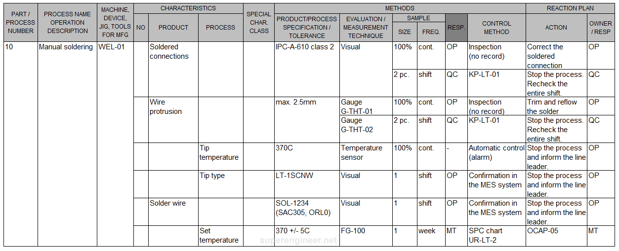
The following example shows a portion of a control plan for the manual soldering process:
The operator (OP) solders wires, creating soldered connections (product characteristics) using a soldering iron. The iron shall have the correct type of soldering tip (process characteristic), and it is set to a constant temperature of 370°C (process characteristic), which is continuously monitored by a sensor in the soldering station.
At the start of each shift, the operator shall check if the solder wire is the correct lead-based solder or lead-free solder alloy. The solder wire also contains flux, so the operator needs to verify the wire's designation (symbol/type).
The operator visually inspects the soldered connections following the IPC-A-610 standard for the relevant IPC product class. Additionally, the operator checks the wire protrusion (max. 2.5 mm) using a G-TH-01 gauge. These inspections are done every time soldering is performed.
A quality control (QC) technician also takes a sample of two products from the process during each shift to inspect the soldered connections and wire protrusion. The results are logged in a record called "KP-LT-01."
Once a week, a maintenance technician (MT) checks the soldering irons to ensure the set temperature on the tip is within the required range of 370°C ±5°C, using the FG-100 device. The results are tracked using the SPC system, with a control chart called "UR-LT-2" as specified in instruction "UR-IS-11." Any issues are addressed according to procedures outlined in document "OCAP-05."
Example of a control plan. The form template according to the AIAG Control Plan 2024. An additional "RESP" column has been added to specify who is responsible for carrying out the evaluation/check. Click to enlarge:
Control Plan - Common Mistakes
As with any document, a control plan is susceptible to various mistakes. In fact, control plan errors are among the most common non-conformities identified during IATF audits. Below are some of the more serious mistakes, in my opinion:
- Focusing only on product inspection. A control plan is not just about product inspection; it also involves monitoring process parameters such as temperature, pressure, machine programming, and tool condition.
- Combining product and process characteristics in one row. This is a common mistake. The methods for supervising product and process characteristics differ, so they should be separated.
- Lack of Error-Proofing verification. According to IATF 16949:2016 requirements, EP systems shall be regularly checked[3].
- Lack of Mistake-Proofing verification. The AIAG Control Plan 2024 requires verification of both EP and MP systems.[1]
- Omitting process steps. A common issue is omitting certain "inconvenient" process steps in the control plan - e.g., temporary processes, rework and repair, etc.
- Lack of linkage to P-FMEA. The control plan should be logically consistent with the previously developed P-FMEA risk analysis.
- Lack of updates after changes. A common problem with many documents in a management system is the lack of updates after process improvements, engineering changes, or corrective actions following the 8D Method or Global 8D.
- Too large, too complex. Many processes today involve high levels of automation, where machines handle multiple measurements, controls, and fault responses. Typically, production is managed by an automated MES system. In such cases, a more general control plan can be developed, which references the MES system rather than listing every inspection detail. This simplifies the control plan, enhances readability, and reduces errors[4].
Standards
- AIAG Control Plan. 1st. 2024. Defines the format and rules for completing the form.
- AIAG Advanced Product Quality Planning (APQP) and Control Plan, 2nd, AIAG, 2008. The most popular manual containing a description of the control plan. Currently being replaced by the latest 2024 edition titled "AIAG Control Plan."
- IATF 16949. Contains several references to the control plan. It helps understand what the control plan should include from the perspective of the automotive parts production process.
- AS 9145: Requirements for Advanced Product Quality Planning and Production Part Approval Process, SAE International, 2016.
- AS 13004: Process Failure Mode & Effects Analysis and Control Plans, SAE International, 2017.
- RM 13004: Defect Prevention - Quality Tools to Support APQP & PPAP, AESQ, SAE International, 2018.
Summary
The control plan is a key document that supports quality management and process stability. It should be linked to the P-FMEA analysis and process flow map to ensure consistency across all documentation. A well-structured control plan includes verification of both error-proofing and mistake-proofing devices.
When developing a control plan, I recommend familiarizing yourself with the new APQP Control Plan 2024 manual. It provides several important recommendations, such as monitoring pass-through characteristics (PTC), managing 100% visual inspections, and implementing automated controls.
A well-written control plan should clearly convey what is being checked at each step of the process, how frequently it is checked, by what means, who performs the checks, where the measurement results are recorded, and what actions are taken if issues arise. It should also be technically accurate, consistent, and easy to understand.
References
- AIAG Control Plan, 1st ed., AIAG, 2024.
- AIAG Advanced Product Quality Planning (APQP) and Control Plan, 2nd ed., AIAG, 2008.
- IATF 16949, International Automotive Task Force (IATF), 2016.
- SI-24, IATF 16949:2016 - Sanctioned Interpretations (SIs), International Automotive Task Force (IATF), 2022
