

Introduction
Soldering is a common method for attaching wires to PCBs and terminals. It is also used in wire-to-wire connections during rework or repair, referred to as a splice.
The article explains wires soldering essentials and requirements defined by IPC standards such as IPC-A-610 and IPC/WHMA-A-620.
Wire, cable, wire harness
The terms wire, cable, and wire harness can sometimes be confusing. Let's clarify what each of them actually means.
- Wire. This is a single metal conductor, which can be solid or composed of multiple strands. The conductor can be insulated or uninsulated.
- Cable. A cable consists of wires, insulated from each other and surrounded by a protective outer sheath. Formally, even a single insulated wire can also be referred to as a cable. Therefore, we can say that a cable has one or more wires.
- Wire Harness. A wire harness is a set of multiple cables or wires (sometimes hundreds), organized in an orderly manner along with connectors, cable ties, tapes, etc.
In the industry, we may encounter various other terms like "circuit," so terminology can sometimes be challenging.
Materials for wire soldering
The high reliability of soldered connections of wires results from using the proper materials, tools, and correct soldering method. Regarding the materials, ensure the following:
- Wire conductors (strands). Avoid the use of oxidized, old wires. Do not use wires with almost black copper strands or covered with green residues. Such strands are highly oxidized and will impact the quality of soldered connections.
- Soldering flux. The soldering flux removes oxides from soldered surfaces, promoting heat transfer. However, too active flux may cause corrosion and electrochemical migration. The careful selection of flux type as a separate material or as part of a solder wire is essential to achieve high reliability. For more details, please read my article about soldering flux in electronics.
- Solder alloy. Select the appropriate lead-free solder or leaded solder, considering legal requirements (e.g., RoHS) and reliability needs. Depending on the composition of the solder alloy, various melting temperatures and mechanical properties are observed.
- Cleaning agent. If the soldered connection requires cleaning, ensure the cleaning agent is safe for cable insulation and does not leave any harmful residue.
Tools for wire soldering
The most important tool for manual wire soldering is the soldering iron. It should have enough power, and the tip must be large enough to achieve proper heat transfer. Additionally, the tip should always be clean to ensure optimal soldering performance.
In certain cases, a hot air gun is another useful tool, which can help shrink the heat-shrinking tubes. Additional tools include insulation strippers, cutters, tinning pots, and various holders, which aid in preparation and precision during the soldering process.
For mass soldering, such as wave soldering used to attach wires to PCBs, it's crucial to ensure that the wave soldering profile is correct to achieve solder connections that meet IPC-A-610 requirements. Additionally, the wire insulation shall remain in proper condition after the process, as described in the IPC-A-610.
Wire or conductor diameter
Some requirements in IPC standards are based on a measure of length expressed in wire diameter unit and sometimes in conductor diameter unit of measure. This distinction is very important in the context of wire preparation and soldering.
- Wire diameter (D). This is the external diameter, measured together with the insulation, designated by the uppercase D.
- Conductor diameter. This is the diameter of complete strands or a solid wire, measured without insulation.
IPC defines various other terms (e.g., strand diameter), so I recommend reading the relevant standards for more information.
Insulation stripping
Insulation stripping is the process of removing a portion of the wire's insulation to expose the conductor. The most common method is mechanical stripping, while thermal stripping is typically used for enameled wires. A third method, chemical stripping, is rarely used and should be applied with caution, and only for solid wires.[1]
After the stripping, check the following aspects[1][2][3]
- Insulation condition. The insulation shall not be frayed, damaged (with no visible copper), or deformed by more than 20% of its original thickness.

- Birdcaging effect. It is a condition where the strands of a wire spread out or flare outward from the conductor, resembling a birdcage. This effect should not occur, or at least should be minimized. IPC has specified different requirements here, depending on the product class.

- Strands damage. The number of damaged strands meets the requirements defined in IPC/WHMA-A-620 Table 3.1[1] or IPC-A-610 Table 6.2[2].
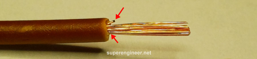
The acceptable condition is shown below:

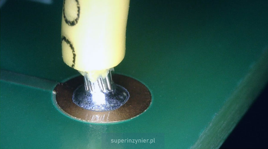
Wire tinning
Tinning is the process of coating a conductor (wire strands) with solder alloy to facilitate proper installation into a PCB hole, attachment to a terminal, or use in certain wire-to-wire connections.
The tinning process involves dipping the exposed copper conductor into a flux and then into a solder pot.
After the tinning, check the following:
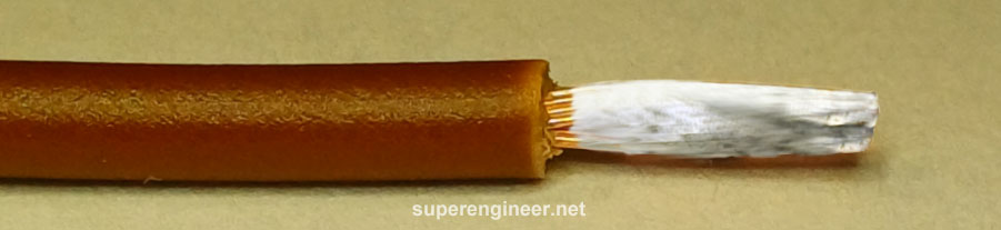
- Solder coverage. The solder should wet at least 95% of the strands' surface that was immersed in the solder pot. Up to 5% of the base metal may remain exposed due to non-wetting or dewetting.
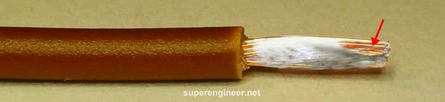
- Solder shape. The solder should form a uniform layer, free of spikes or deformations that could interfere with wire installation.
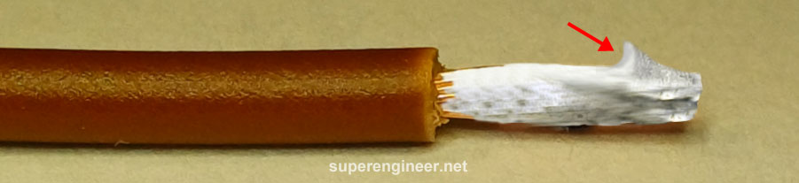
- Distance to insulation. The solder may penetrate slightly under the insulation, but it should not wet the part of the conductor that should remain flexible (for example, the part that will be bent during assembly). The maximum distance of solder from the insulation for Class 3 is 1D. Classes 2 and 1 have more relaxed requirements.
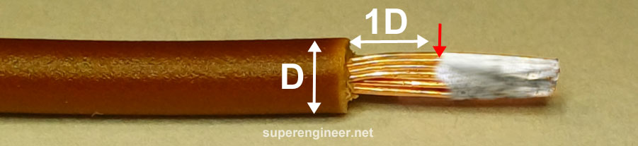
The acceptable condition is shown below:
Note: Wire tinning is not allowed for wires used in crimped connections or wire-to-wire junctions known as a "mesh splices."
Wire soldering to PCB
When soldering wires to a PCB, the following requirements should be met:
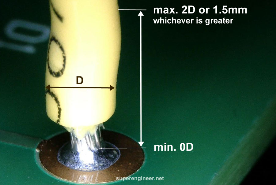
- Insulation distance. The distance between the wire insulation and the soldered connection should be between 0D and 2D or 1.5mm, whichever is greater. A greater distance is considered a defect for Class 3 products.
- Insulation condition. The insulation shall not be charred, burned or melted with the solder joint (shall not disturb the solder joint). It may be slightly deformed and melted.
- Solder joint quality. It should meet the requirements of Section 7.3.5 of the IPC-A-610 standard. These requirements vary depending on the class of the product. For example: For Class 3 products, the vertical fill should be at least 75%. The source-side land coverage should be at least 75%, and the circumferential wetting shall be at least 330°. On the destination side, circumferential wetting shall cover at least 270°, and land coverage may be 0% (no coverage at all).
An example of soldering a wire to a PCB. The criteria for the distance of the insulation from the solder joint are provided:
Need more details about IPC classes and soldering/installation conditions? Read articles: IPC product classes and Conditions in IPC standards.
Wire soldering to terminal
There are two kind of terminals. The first kind is a metal part swagged to the PCB, and the other kind are metal pins of connector. Depending on the terminal type, there are various IPC requirements.
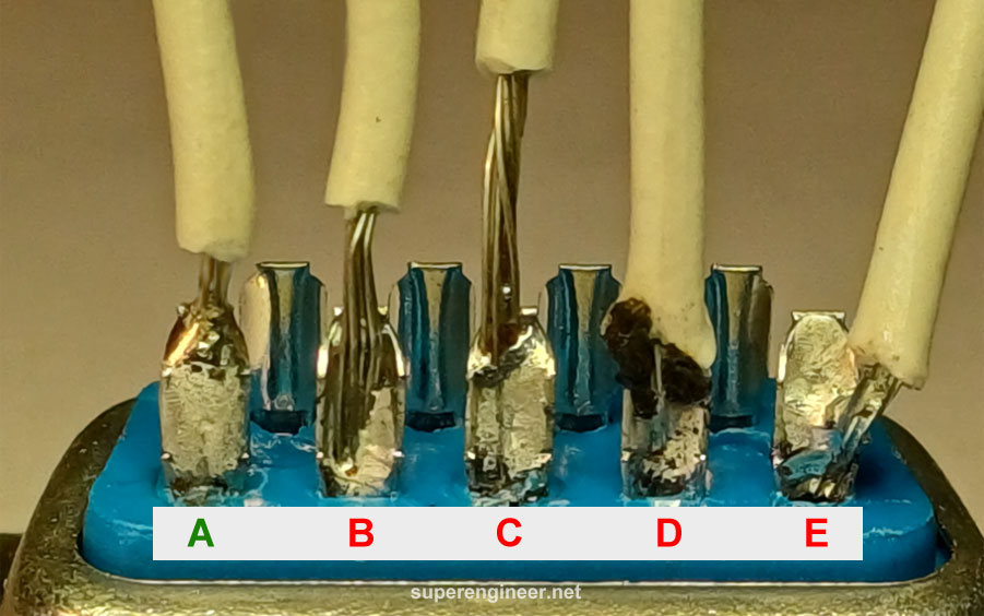
As an example, soldering requirements to "cup terminal" is shown.
- Solder fillet. Minimum 75%.
- Insulation distance. From 0D to 2D or 1.5mm, whichever is greater.
- Wire position. It is preferred when the conductor is in full contact with the terminal wall and base.
The following example shows the soldering of wires to cup terminals in a 9-pin D-Sub connector. Only the soldered connection at point "A" manages to play by the rules. The rest? Let's just say they're a "soldering catastrophe" waiting for a disaster documentary series...
Splices
Splices (wire-to-wire) soldering per IPC/WHMA-A-620 standards has several options:
- Mesh splice. Wirers must not be tinned. Interlocking of conductors between 3D to 5D.
- Wrap splice. Minimum three wraps of each conductor.
- Hook splice. Minimum three wraps of each conductor.
- Lap splice. Wire laps minimum three conductor diameters.
- Heat Shrinkable Solder Device. This component combines a solder alloy ring and two sealing rings inside a heat-shrink tube, simplifying the creation of a sealed, soldered electrical connection between two wires.
After soldering the splices, they should be secured with heat shrink tubing.
Soldered splices in certain applications are a very bad idea. Vibrations and various thermal stresses can cause soldered connections to crack, so using this type of connection can be problematic. Sometimes, it is better to use crimped splices like Butt Splice, etc.
Example of a wrap splice (before soldering):

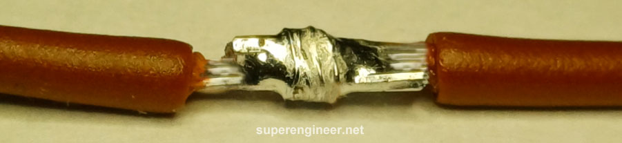
Example of a lap splice (after soldering):
More information on splice evaluation can be found in the IPC/WHMA-A-620 standard.
Strain relief
When the wires are installed and soldered, ensure sufficient strain relief. The wire should not be under strain, which could cause the solder joint to crack over time.
Standards
Several industry standards define the requirements for wire soldering:
- IPC-A-610. Acceptability of Electronic Assemblies.
- IPC/WHMA-A-620. Requirements and Acceptance for Cable and Wire Harness Assemblies.
- IPC-J-STD-001. Requirements for Soldered Electrical and Electronic Assemblies.
- MIL-STD-2000. Standard Requirements for Soldered Electrical and Electronic Assemblies.
Summary
High quality soldered wire connections are the result of proper material selection, the use of adequate tools, and the application of appropriate assembly method. Following industry standards like IPC-A-610 and IPC/WHMA-A-620 helps achieve reliable wire solder connections in a wide range of applications.
Footnotes
- IPC-A-610 "Acceptability of Electronic Assemblies", Rev J, Bannockburn, IL, USA: IPC, 2024.
- IPC/WHMA-A-620 "Requirements and Acceptance for Cable and Wire Harness Assemblies", Rev E, Bannockburn, IL, USA, IPC, 2022.
- IPC-J-STD-001 "Requirements for Soldered Electrical and Electronic Assemblies", Rev J, Bannockburn, IL, USA: IPC, 2024.
