Introduction
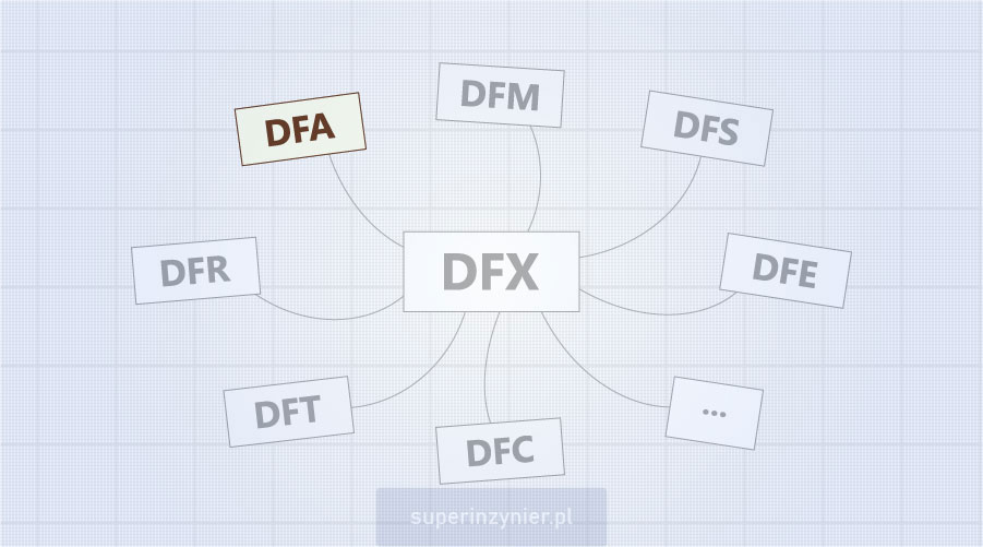
Design For Assembly is part of a much broader concept called Design for Manufacturing (DFM), which is also part of an even broader concept called DFX: Design For Excellence. The entire DFX (and therefore also DFA) is a set of technical recommendations[1] that can be applied when designing a product to optimize it.
Design For Assembly focuses on product design aspects to simplify the assembly process.
Implementing Design for Assembly (DFA) techniques can significantly enhance the cost-effectiveness of a product, demonstrating a strong correlation with the principles of Design for Cost (DFC).
Interesting fact: Elon Musk uses Design for Assembly as part of his design method. Please read the full article about it: Five-step design method by Elon Musk.
Main aspects of DFA
DFA recommendations may be divided into several general categories, each containing industry-specific guidelines. Consider the following categories:
Elimination of process steps
Implement design solutions to eliminate some process steps. Such an action can result in significant savings. Examples:
- Using components that allow automatic assembly eliminates the manual labor-intensive process.
- Replacing a large THT capacitor with several smaller SMD capacitors eliminates the THT soldering process and the requirement for additional attachment to the PCB with RTV silicone. It allows the elimination of the THT soldering and RTV gluing process.
Elimination of parts
Eliminating parts is an ideal solution, but it is only sometimes possible. Removing parts from a project reduces its cost and, of course, simplifies the assembly process. There is an excellent technique for removing parts from a project, referred to as trimming, which is one of the elements of the TRIZ method. For example:
- Use "pull-up" resistors inside the MCU and remove external (discrete) resistors from the design that perform this function. It is an example of "delegating the function" from the discrete resistors to the MCU. Now, designers may remove the discrete resistors.
Standardization of parts
Part standardization involves selecting one type of a part that can replace several similar variants. Sometimes, this can increase the cost of components; however, the total cost will be lower. It removes activities like procurement of various parts, storage at multiple locations, and the cost of assembly errors. Examples:
- Standardization of screw lengths.
- Standardization of SMD resistor tolerances. 5% and 1% parts standardized to 1%.
Symmetrization of parts
Symmetrization involves changing the geometry of a part so that the direction of its assembly in a product is arbitrary. It eliminates potential defects in the process and the costs associated with reworking, repairing, or scrapping nonconforming products.
Asymmetrization of parts
It is the exact opposite of the symmetrization. A completely asymmetrical part eliminates the possibility of reverse assembly.
Adding a feature to a part
Adding some additional features (e.g., base hole, color change, etc.) to implement an error-proofing or mistake-proofing solution. These techniques are often referred to as Poka-Yoke.
Industry specyfic aspects
Depending on the particular industry, many specific recommendations are related to DFA. In the case of electronic device design, an essential aspect of DFA is a proper PCB layout (placement of tracks and components on the PCB). Examples:
- Maintain appropriate distances between components on the circuit board. It facilitates SMT/THT assembly and the electronics soldering process.
- Ensure proper component orientation for the wave soldering process. It reduces the risk of solder bridges or insufficient solder joints.
- Place parts at adequate distances to avoid a "shadowing" effect in the wave soldering process.
- Ensure proper clearance from the board edge to allow safe clamping of the PCB during the assembly process.
- SMD and THT solder land geometry should follow IPC standards or recommendations from particular component manufacturers.
- And many other guidelines.
Standards and Guidelines
I recommend getting familiar with the industry design standards. In electronics manufacturing, we can find such recommendations, among others, in documents developed by the IPC organization. For example:
- IPC-2220 (a series of documents related to PCB design)
- IPC-7351 Generic Requirements for Surface Mount Design and Land Pattern Standard
- IPC-7352 Generic Guideline for Land Pattern Design
- IPC-7093 Design and Assembly Process Implementation for Bottom Termination Components (BTCs)
- IPC-7095 Design and Assembly Process Implementation for Ball Grid Arrays (BGAs)
Knowledge of manufacturing processes
Designers should understand the assembly process of the products they design. I recommend a thorough understanding of the various assembly methods, their limitations, and typical quality problems. It is an excellent thing if designers have direct contact with the team producing the product.
In my opinion, the ideal situation is when designers spend time working on the process, learning about assembly techniques and their limitations, the challenges and risks associated with rework or repair, and the scrap costs associated with inadequately designed products.
Summary
DFA - Design For Assembly is a great way to reduce costs and improve quality in the assembly process through proper product design. Knowledge of basic DFA recommendations is a very valuable skill for a professional designer. A key aspect is a good understanding of manufacturing processes and using industry-specific standards related to Design For Assembly.
Footnotes
- PMBOK Guide, rev.6, Project Management Institute Inc. 2017


